The LimeNET Micro has received a few upgrades since its crowdfunding campaign, now in its last two weeks, launched, including considerably improved RF bandwidth, active Power-over-Ethernet (PoE), and both DSI and HDMI display connectivity.
Designed to meld the LimeSDR with the Raspberry Pi Compute Module 3 to create a fully-standalone software defined radio (SDR) and general-purpose processing (GPP) platform, the LimeNET Micro as originally designed saw the LMS7002M field-programmable radio frequency (FPRF) hardware interfaced with the Raspberry Pi via the Serial Peripheral Interface (SPI) bus, limiting its bandwidth to less than 1 MHz. Following community feedback, the decision was made to switch to USB connectivity – boosting the maximum bandwidth to 10 MHz receive-only and 5 MHz in full-duplex mode, though real-world performance will vary depending on what other processing tasks the Raspberry Pi is handling at the time.
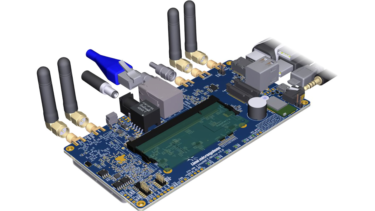
At the same time, the board itself was redesigned: the new LimeNET Micro v2.0 includes the additional Camera Serial Interface (CSI) and Display Serial Interface (DSI) connectors, active Power-over-Ethernet (PoE), an HDMI port, analogue audio port, and two USB ports from the original’s single-port design – allowing a keyboard, mouse, and display to be quickly connected to the LimeNET Micro to turn it into a fully-functional desktop.
The crowdfunding campaign has just under two weeks left, with more information available on the Crowd Supply page.
The MarconISSta project, which has put a LimeSDR on the International Space Station (ISS) in order to map global radio frequency usage, continues to gather data – including some measurements outside of the Very High Frequency (VHF) bands.
“The constant signals at 137.5 MHz, ~137.2 MHz etc are self-induced artefacts,” writes project lead Martin Buscher in the latest update, showing off a series of waterfall plots generated from the data recorded over the past couple of weeks. “From 11:30 there is a lot of activity and for some signals the frequency changes. Normally, the frequency of signals is higher during approach of the source, while it is lower while moving away. For some of the signals, this ‘Doppler shift’ is in the opposite way than expected. Any idea what this is? We do. One hint: It keeps recurring over various parts of the world, mainly over North America.”
The full update and associated waterfall plots, plus any future updates, can be found on the official project page.
Radio amateur and computer engineering student Luigi Freitas has demonstrated a software defined Doppler radar project, based around a LimeSDR Mini and capable of measuring linear speed and displaying it via Fast Fourier Transform (FFT).
“[A] video test of my 2.4 GHz Software Defined Doppler Radar using a LimeSDR Mini,” Luigi writes of his demonstration via social networking service Twitter. “It can measure the linear speed of the fan’s blades and display the Doppler Shift using an FFT. It can do other tricks too.”
The full demonstration video is available via Twitter, while Luigi has promised a full write-up will appear on his personal blog in the near future.
Researchers at the ETH Zürich have published a paper which could prove a breakthrough for millimetre wave (mmWave) last-mile communications, demonstrating the conversion of wireless signals into optical signals using no electronics whatsoever.
The traditional reception path for a millimetre wave signal sees the wireless signal hit an antenna, then an amplifier, before being mixed down to baseband frequencies and sent to a light modulator for transmission along optical fibres. Professor Jürg Leuthold and his team have come up with an alternative, which does away with most of what would be recognisable as a receiver – including power sources and electronics.
“That makes our modulator completely independent of external power supplies and, on top of that, extremely small so that it can, in principle, be mounted on any lamppost,” explains PhD student Yannick Salamin of the project. “From there, it can then receive data via microwave signals from individual houses and feed them directly into the central optical fibre.”
The system’s heart is a tiny, sub-millimetre chip which houses a microwave antenna and converts the incoming millimetre-wave signals to electrical impulses. These impulses act on a thin slot located at the centre of the chip, measuring a few micrometres in length and less than hundred nanometres in width, which is filled with an electrically-sensitive material and which interacts with light from an optical fibre to propagate the signal as plasmons. As the plasmons reach the end of the slit, they’re converted back to light waves but with the information received from the millimetre wave signals encoded – at rates, the project claims, of up to 10 gigabits per second (Gb/s) over five metres and 20 Gb/s at one metre.
The team’s work is available in the journal Nature Photonics under the title “Microwave plasmonic mixer in a transparent fibre-wireless link.”
Hackaday has highlighted a visual guide by Mare & Gal Electronics on the creation of ultra-compact “rubber-ducky” helical antennas for the 868 MHz band, using salvaged coaxial cable.
“This simple Helical Antenna can be used for most LoRa (and other small wireless device) applications,” Mare explains in the post, “where space constraints exist. The construction is simple, made from wound solid Ag plated copper wire taken from piece of coaxial cable.”
Advice given in the guide includes subjecting the salvaged copper wire to “short, fast, strong pulls – this will make copper wire stronger,” and to wind the rod around a 5mm metal rod or drill bit to shape it. The most challenging part, by far, is in the extension stage: after cutting at the seven-turn point, the antenna must be extended to 14mm in length with every turn having a 2mm gap. “Uneven pitch,” Mare warns, “will result in poor quality.”
The full guide is available on the Mare & Gal Electronics blog.
The Es’hail 2 satellite, designed for amateur radio use by hams from Brazil to Thailand, has been successfully launched and deployed on the back of a SpaceX Falcon 9 rocket, though is not expected to become available for use for another month or two.
Built by Qatari company Es’hailSat, Es’hail 2 is positioned at 25.5 degrees East and carries a 2.4 GHz Phase 4 transponder, a 10.45 GHz Phase 4 transponder, 250 kHz linear transponder, and an 8 MHz transponder for experimental digital modulation schemes and amateur DVB broadcasts. The satellite was successfully launched on the 15h of November on a SpaceX Falcon 9 rocket launched from Kennedy Space Centre, and is now undergoing commissioning.
“First of all, all systems and payloads of the satellite have to be subjected to a thorough inspection, one also speaks of ‘in-orbit test’ and ‘in-orbit verification,'” explains AMSAT-DL president Peter Gülzow in a blog post on the subject. “This involves checking all the parameters and specifications previously defined by the satellite manufacturer together with the customer, including, for example, compliance with the frequency spectra of the high-power transmitters. Only when all tests and measurements have been completed is the satellite officially handed over to the operator, the Es’hailSat – Qatar Satellite Company. This also includes the two AMSAT transponders!”
Peter asks radio enthusiasts to “start with own transmission attempts only after the official release [announcement confirming commissioning is complete]. Transmission attempts before a release only hinder the commissioning and could lead to delays.”
The ZACube-2 CubeSat, meanwhile, has received its own launch schedule, and is to be hoisted into orbit on board a Soyuz launched from Baikonur, Russia, on the 25th of December – making a very merry Xmas for the French South African Institute of Technology (F’SATI).
The ZACube-2 triple-unit CubeSat includes two primary payloads: an automatic identification system (AIS) receiver based on a software defined radio and designed to track ships’ locations, registration information, speed, and directional travel throughout South Africa’s economic zone, and an advanced fire detection camera for finding and monitoring forest and veldt fires in the region.
More details on the project can be found on Space in Africa.
Finally, the US National Oceanic and Atmospheric Administration (NOAA) has confirmed the final positioning of the GOES-17 satellite, sharing the first images from its Advanced Baseline Imager (ABI).
Joining NOAA’s Geostationary Operational Environmental Satellite (GOES) constellation, GOES-17 reached its final orbital position of 137.2 degrees West earlier this month and began transmitting its first high-resolution images on the 13th of November. Featuring the same imaging hardware as the GOES-16 satellite, GOES-17 provides visible and infrared imagery in GeoColor and 16 different channels, and will become the operational GOES West satellite on the 10th of December. The data provided before this date, NOAA warns, should be “considered preliminary and non-operational.”
More information, and the first imagery, is available on the NOAA website.