Power amplifiers (PA) are nonlinear devices and their linearisation is highly desired for a number of reasons. In the case of radio frequency (RF) PAs, linearisation improves power efficiency and subsequently reduces running cost of the wireless infrastructure.
Considering the PA performance for a given air interface, adjacent channel power ratio (ACPR) and error vector magnitude (EVM) are the key considerations to provide support for sophisticated modulation schemes, multicarrier signals, and high modulation bandwidths.
This solution for PA linearisation has been developed by Lime Microsystems and is based on adaptive digital predistortion (ADPD).
The structure, implementation and measured results are summarised here and for more detailed information please see the wiki page.
LimeAPDP structure
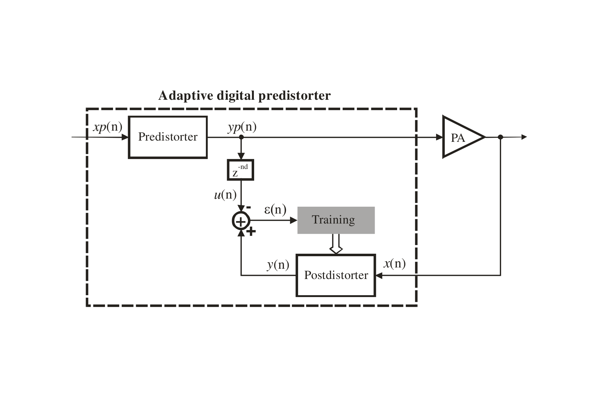
Indirect learning architecture
The simplified block diagram of an indirect learning architecture is shown above. Please note that the RF part in neither the TX (up to PA input) nor RX (back to base band frequency) paths are shown for simplicity.
Delay line compensates ADPD loop delay. The postdistorter is trained to be inverse of power amplifier. The predistorter is a simple copy of postdistorter. When converged:

Hence, the PA is linearised.
Complex valued memory polynomial
The LimeADPD algorithm is based on modelling a nonlinear system (PA and its inverse, in this case) by complex valued memory polynomials. These are, in fact, cut versions of Volterra series, an approach well known for general nonlinear system modelling and identification. Here, “cut version” means the system can efficiently be implemented in real life applications.
Implementation platform

The ADPD algorithm is implemented using a LimeSDR-QPCIe board. This board has a lot more options than shown, including two LMS7002M chips, a USB interface, GPS receiver…) The LMS7002M itself is a 2T-2R RF IC. For clarity, the block diagram shows the minimum hardware options required to illustrate the LimeADPD implementation. The same signal names as in the previous figure are used here.
For development or demonstration, a test waveform is uploaded first and played from the WFM RAM Block. Initially, the predistorter is bypassed. The predistorter has provision for SPI in order to update the coefficients during the training. Signals xp, yp and x are captured using Data Capture RAM Blocks. Captured data is made available to the (Intel Motherboard) CPU Core via the PCIe interface. The CPU implements the postdistorter block, delay line, and the rest of training algorithm. After each adaptation step the CPU updates predistorter parameters via PCIe/Stream SPI.
In real applications WFM and xp Capture RAM blocks are not required. The algorithm needs only yp and x as shown in the LimeADPD structure. The CPU Core performs both ADPD adaptation, as explained above, and baseband (BB) digital modem functions which are application specific, for example Long Term Evolution (LTE).
Measured results
 A measured EVM of 3.24% with LimeADPD, down from 6.58% without.
Before implementation and measurements, the ADPD algorithm has been thoroughly simulated. Simulation results are omitted from this document for the sake of clarity. ADPD performance has been measured and the results for the first case is summarised. For further details, including EVM and ACPR comparisons for this and a second test case, please see the wiki page.
Test case 1
- Moderate output power amplifier device Maxim Integrated MAX2612.
- Psat ~ 19dBm.
 No ADPD – yellow trace. With ADPD – blue trace. IMD3 and IMD5 distortion components at the PA output reduced by almost 20 dB.
The LimeADPD algorithm has been confirmed by measured results. ADPD is capable of cancelling any distortion above system (DACs -> TX -> PA -> Coupler -> Attenuator -> RX -> ADCs) noise floor.
For Test Case 1, at the antenna point (PA output) ACPR is improved from -34 dBc (out of spec.) to -51 dBc (well within the spec.) EVM is improved from 6.58% to 3.24%.