LoRa is a chirp-based modulation format that can operate beneath the noise floor. Its robust, low power, and low rate — and a candidate technology for connecting the Internet of Things. In this blog I will cover the basics of LoRa modulation, show off the LoRa PHY blocks for Pothos, and demonstrate simple relay and client applications using a pair of LimeSDRs.
TLDR; = scroll down for the demo videos!
LoRa Modulation basics
The LoRa modulation is defined by 3 main parameters: spread factor (SF), bandwidth (BW) and carrier frequency. The job of the modulator is to translate symbols consisting of SF bits into chirps that span 2^SF samples at the specified sample rate (BW). A chip is simply a tone that sweeps from -BW/2 to +BW/2. Transmit symbols are modulated into the chirp by circularly shifting the base chirp waveform. Therfore SF bits in the input symbol translate into 2^SF unique shifts of the base chirp waveform.
An important aspect of the modulation is that for every additional symbol bit, we double the number of output samples needed to modulate a symbol. This makes a LoRa a very slow modulation with packets taking 100s of milliseconds to transmit. However, this redundancy also makes LoRa a very robust modulation capable of being demodulated beneath the level of the noise floor. The following plot demonstrates several symbols being modulated into chips. Frequency demodulation is a useful way to visualise this waveform because it shows the shifted chirps as simple ramping waveforms.
 Demodulation techniques
LoRa demodulation is fairly straightforward. First de-chirp the waveform my multiplying by the conjugate chirp, this turns each modulated symbol into regions of constant frequency. Next take the FFT of each region. The location of the peak bin in the FFT (also known as argmax) will tell us the value of the symbol, even in the presence of very high noise. This is how 2^SF FFT bins become transformed back into SF bits which compose the index of the FFT bin.
But wait! We can’t extract symbols yet, without first aligning to the received chips. Fortunately, the transmitted sequence includes a long detect sequence composed of multiple base chirps. Without knowing the alignment offset, we can simply perform the same detection sequence with the conjugate chirp and the FFT. The measured value will tell us the shift of the chirp — which in this case, tells us show much to shift in time to achieve alignment. In addition, a transmitted frame will also contain known frame synchronization symbols to establish the first symbol of a frame.
The following plot demonstrates the down-conversion of the chirps. An intentional partial chirp was inserted to demonstrate the technique of synchronizing to the detect sequence. And again, the frequency demodulation comes in handy again to visualise the regions of constant frequency.
 And here we can see the recovered symbol encoded as the peak index in the FFT. Note that this is an idealized demonstration and in practice these index measurements will differ by +/- 1 position. Fortunately, the decoder has multiple ways to recover from single position errors.
Digital encoding
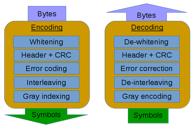
Another aspect of LoRa is how arbitrary payloads of bytes are encoded into packets of transmit symbols and decoded back into bytes. The encoding and decoding process is split into several smaller actions, each of which is reversible and may offer its own configuration options. The decoder process is basically the reverse of the encoder, so we will cover the encoder steps in order here:
- Whitening is an optional step that can take the form of Manchester encoding or scrambling. The job of whitening is to ensure that there are no long stretches of all 0’s or all 1’s in the payload that may bias the signal in some way.
- A header and CRC are added to encode the length of the packet and the checksum of all bytes in the packet. The header can potentially specify the encoding parameters so that the decoder can operate blindly without configuration hints.
- Every nibble of the input payload is transformed into a codeword with additional error coding bits — the number of redundant bits (RDD) is configurable from 0 to 4. Using Hamming(4, 7) codes and Hamming(4, 8) with additional parity bit we can correct single bit errors.
- Interleaving is a process of distributing bits from the codewords into the output symbols. Each codeword contains 4+RDD bits, and each output symbol contains SF bits (the spread factor). Therefore it takes SF codewords to produce every (4+RDD) symbols. Its also possible to use a reduced symbol set where the output symbol uses less than SF bits. In this case the packet takes more time in the air but gains increased resilience to measurement error.
- Finally, the output symbol is Gray decoded to produce the actual value used to shift the base chirp. Notice that this is the opposite process of Gray encoding. When the demodulator measures the frequency, its very likely to exhibit a +/-1 measurement error. Gray encoding the received symbol basically converts this small measurement error into a single bit error which can be easily handled by the error correction.
Using LoRa in Pothos
The MyriadRF LoRa-SDR repository provides modulation and encoding blocks for Pothos that implement the techniques explained above:

- LoRa modulator: The modulation block accepts a packet of transmit symbols and performs the chirp modulation. Detect and frame synchronization symbols are inserted as well.
- LoRa demodulator: The demodulation block accepts received samples from a SDR source block and performs demodulation searching for the frame sync and extracting a packet of symbols.
- LoRa encoder: The encoder block is responsible for encoding the user’s payload of bytes into a packet of transmit symbols using configurable bit-rate, error correction, and spreading factor.
- LoRa decoder: The decoder accepts a packet of received symbols from the demodulation block and performs decoding and error correction. Bad packets can be dropped when they fail CRC.
- SDR Blocks: The waveform bandwidth and carrier frequency are specified by the sample rate and centre frequency of the SDR blocks.
Notes on the completeness of the LoRa phy blocks: As of posting this blog, the LoRa demodulator block is capable of demodulating and synchronizing to the waveform transmitted by the RN2483. However the decoder does not currently match the exact header and bit patterns exhibited by the RN2483. More work will be needed on the encoder and decoder blocks to support the exact packet format used by the RN2483 and possibly other existing LoRa-capable devices. The reversing LoRa document by Matt Knight is an excellent breakdown of the decoding process and should help to close this gap.
Modem and channel simulation
The following screencast demonstrates the use of the Pothos LoRa blocks in a loop-back environment and how added noise affects the system. The topology used in the screencast can be found in the LoRa-SDR examples directory.
LoRa relay with LimeSDR
In this replay demonstration, I show two PCs exchanging messages over the LimeSDR using the LoRa blocks. The first PC will act as a simple relay, demodulating and decoding LoRa packets and re-encoding and re-transmitting the packets using a different synchronization word and frequency. The second PC will be a manned client which will transmit messages based on user input and receive them back re-transmitted through the relay.
Conclusions
LoRa was an interesting protocol to learn about. I found the chirp demodulation technique intriguing yet simple, and I enjoyed understanding the design trade-offs for robustness vs. over-the-air time. Moving forward, I think the demodulator may be able to benefit from some additional synchronization tweaks; and I would like to improve the encoder and decoder blocks to be able to handle the format for off-the-shelf LoRa chips such as RN2483. It would be also interesting to see what sort of line-of-sight distance can be achieved with LimeSDR using higher transmit power comparable to an existing LoRa solution.
References:
- https://en.wikipedia.org/wiki/Chirp_spread_spectrum
- https://en.wikipedia.org/wiki/Hamming_code
- https://en.wikipedia.org/wiki/Gray_code
- https://revspace.nl/DecodingLora
- http://www.jailbreaksecuritysummit.com/s/Reversing-Lora-Knight.pdf