The Reference Development Kit (RDK) provides a highly flexible platform for digital designers and software developers, enabling them to create wireless systems without the need for RF design skills. It also serves as a reference model to accelerate the creation of complementary boards and integrated solutions, with the KiCAD designs, manufacturing files and documentation being made available for use under a liberal licence.
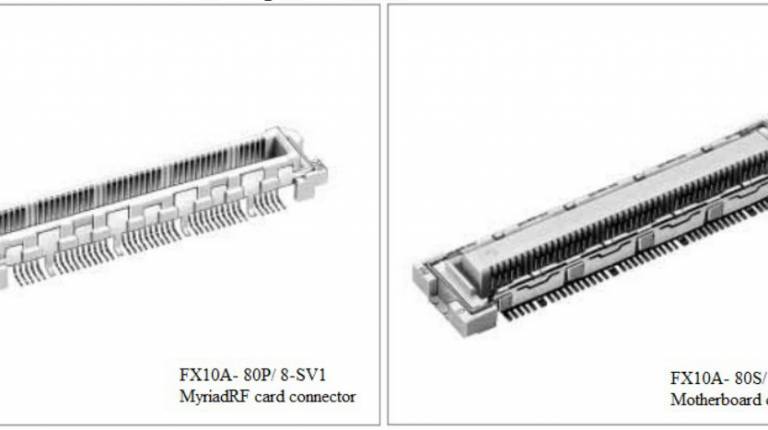
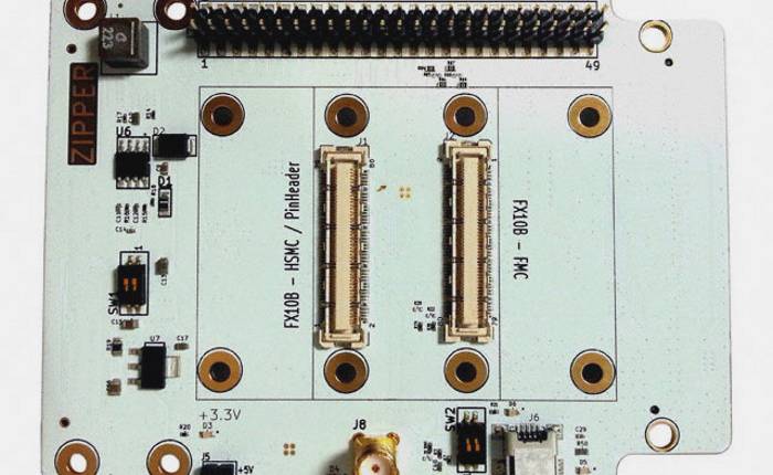
The RDK is centred around a family of transceiver modules that are used together with interface boards or a suitable host system, via an RFDIO or uRFDIO connector.
Myriad-RF 1
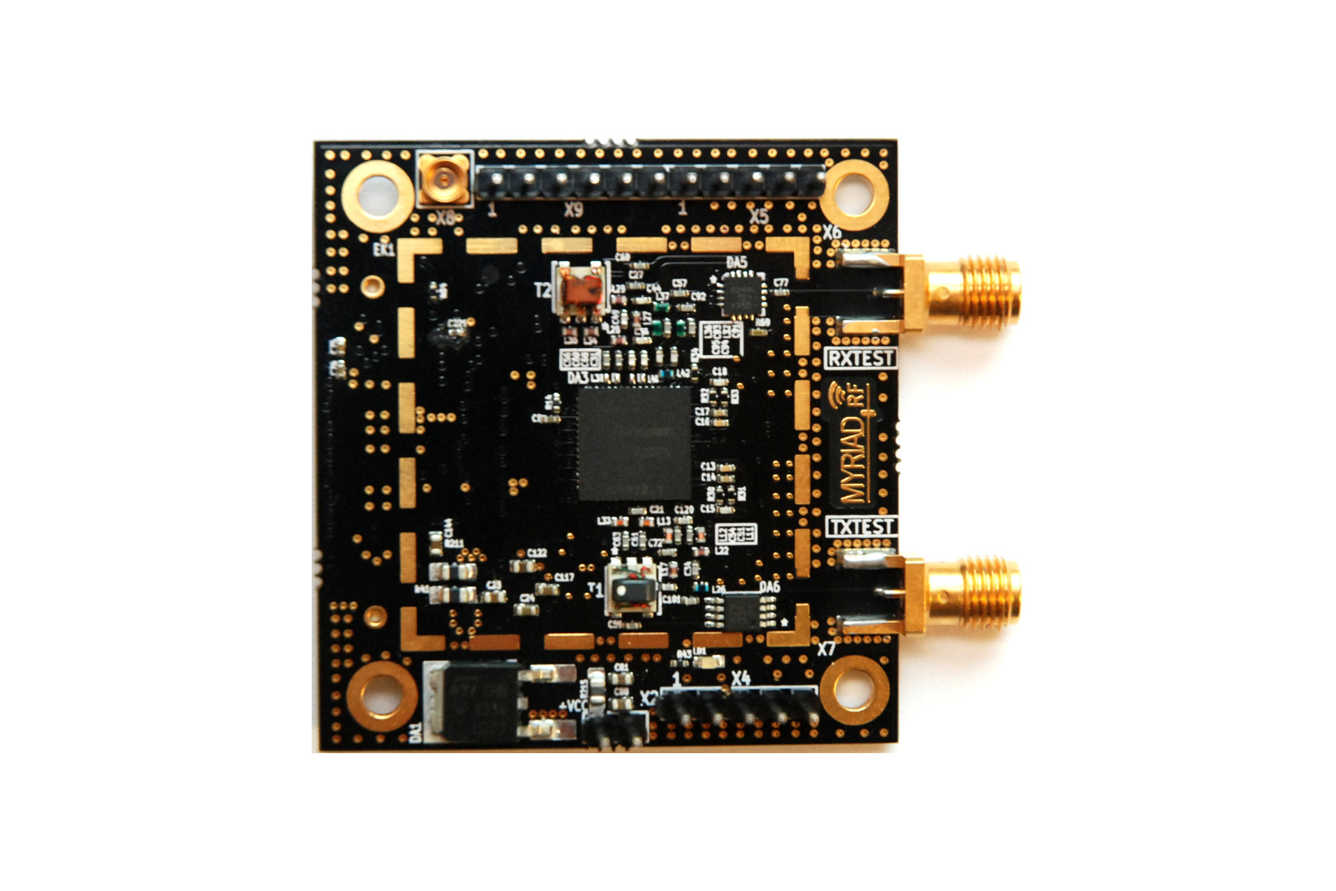
The original Myriad–RF 1 board is a multi-band, multi-standard RF module, based on the LMS6002D transceiver IC by Lime Microsystems. It has one RF broadband output, one RF broadband input with digital baseband interface, established via the RFDIO connector. The board also provides the user with pin headers for power supply, reference clock, analog I/Q input/output and SPI interface connections. It contains everything needed for it to be connected to baseband (BB) chipsets, FPGAs or to run in an standalone mode.
The Myriad-RF 1 board enables developers implement their products for a wide variety of wireless communication applications quickly and efficiently, given the flexibility of the solution. In addition, the designer can make use of the freely available ready-made board implementation, modify and manufacture to accelerate the development time.
RF module controlVia SPI interface
| Transceiver | LMS6002D |
| RF bandwidth | 300 MHz to 3800 MHz |
| Baseband bandwidth | Programmable (16 selections); 0.75 – 14 MHz, Bypass mode |
| Analogue inputs | I/Q differential input for transmitter |
| Analogue outputs | I/Q differential output from receiver |
| Reference clock frequency | 23 – 41 MHz |
| Input voltage | 5V (recommended) |
The figure and table below provide key Input/Output configurations, connector assignments and descriptions. The analog differential IQ interface is available on Myriad-RF board and provided via X3 and X4 connectors. X6 and X7 are the RF connectors for receive input and transmitter output, clearly marked in the picture. The board is tuned to support band 1 (Tx 2140 MHz and Rx 1950 MHz) as well as broadband operation. The front end switches are configurable for selecting Receiver inputs and Transmitter outputs via GPIO’s which in turn can be controlled via the X3 connector.
Communication
The LMS6002D register are controlled via SPI interface. The SPI interface can be established via digital connector X3 or external connector X9.
Configuration
The Myriad-RF 1 board is pre-configured to work on UMTS band-1, the most common band used by 3G communications equipment. By connecting the device to a computer it can be configured to run on any mobile frequency band or standard, by setting up the LMS6002D registers to the required frequency, gain or BB bandwidth setting using LMS Suite.
uMyriadRF-6002
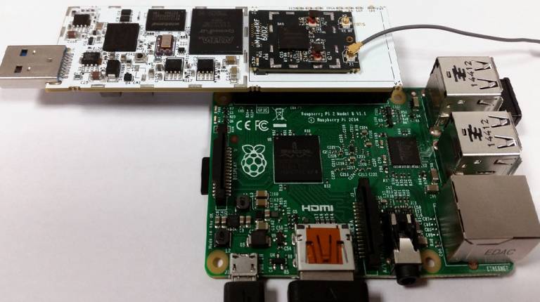
The uMyriadRF-6002 is the first in the micro series of transceiver modules and provides an incredibly compact form factor version of the original Myriad-RF 1 board. This can be seen pictured above — a small black PCB assembly with a coaxial cable connected — plugged into the uSTREAM board, which is in turn connected to a Raspberry Pi 2 Model B SBC.
uMyriadRF-LMS7002
This is the LMS7002M variant of the micro transceiver module.
