Receiving ASK/OOK signals in Pothos and GNU Radio.
Welcome to the sixth instalment of LimeSDR Made Simple. Last time we looked at transmitting and receiving ASK (amplitude shift keying) signals in Octave. However, we mostly glossed over the modulation and techniques involved.
In the next post(s) we will look at both receiving and transmitting single level ASK, which is often referred to as on-off keying (OOK). This is simple to understand and commonly used in things like doorbells and garage door openers.
A little more hardware is required if you wish to follow along this time and a 433MHz (UHF) ASK/OOK device will be required. If you have a gate/door/garage fob, then this will likely be sufficient.
The usual warnings apply around removing the antenna from any unused TX ports to avoid accidental transmissions. As always, proceed with caution and staying legal will avoid jamming the neighbours doorbell, which is a bonus!
ASK in detail
Warning, communications theory ahead! As discussed previously, ASK is the most simple of modulation techniques. The most basic implementation of ASK is the presence of a tone signify a one and no tone indicate a zero. This is OOK, with 2 levels: on and off. The tone is usually the carrier frequency, which in our case will be 433.9MHz (more how to get this later).

As promised a very simple protocol on the surface — so simple it can be directly viewed on a sufficiently fast oscilloscope and decoded by eye.
Like most simple ideas there are a few other things that we need to know about. Due to realities of radio reception our circuits take time to lock and adjust frequency/gain. This is true of both SDR and traditional circuits. Taking a keyfob as an example: the exact TX frequency of these fobs is quite often a little “loose” and the centre frequency can drift.
Frequency drift
In the analogue domain this would be dealt with by some form of control loop locking to the carrier and adjusting the receive circuit to match. A PLL or a simple self-resonant circuit is common, but the theory of operation is the same in the grand scheme. In a SDR, this can be done the same way or somewhat ignored until later at the expense of digital filtering or co-channel rejection. This is assuming we have sufficient captured bandwidth in the first place. In reality, with the right receiver ASK is very immune to frequency drift and phase changes, so this is not normally worried about.
Gain
Amplitude is a problem in both traditional and SDR circuits. Eventually it will need to be dealt with via some form of gain control. AGC (automatic gain control) is best, but manual settings can work.
In hardware this can be adjusting an LNA and in software multiplying the signal. Both have their merits.
Preamble
To deal with both locking to the signal and gain, we cannot start receiving data the very pico-second the carrier is applied. The gain control and frequency control will need time to lock. The solution is to produce a preamble — in simple terms, a period of signal that will allow the receiver to lock before actual data is passed. This technique is not limited to RF communications and the device that you are reading this upon is probably doing a preamble millions/billions of times per second, as it’s a requirement of DDR RAM to account for PLL lock time (just like the RF receiver).
Finding out the frequency
We will be using a wireless key fob bought from eBay as the ASK source to decode. In Europe these fobs typically use the licence exempt 433MHz band. However, to effectively decode we need to find the exact frequency of the part.

Using LimeSuiteGUI this a simple task and just as in instalment two <link> we can use the FFT viewer to measure the frequency of transmission. By changing the SXR frequency to 433MHz we can get an FFT plot and when pressing the fob a new peak should appear. By retuning until this new peak is in the centre, we can find the frequency of the fob. Ours was on 433.9MHz.
Designing a receiver for SDR
So far in the series we’ve used existing designs and re-created an FM radio using Josh’s example for guidance. Time for the next step: original works!

Looking at a generic receive chain we will need to implement the receiver, some gain either in the receiving element or the digital domain (or both), and finally we will need to detect the waveform and turn this back into data.
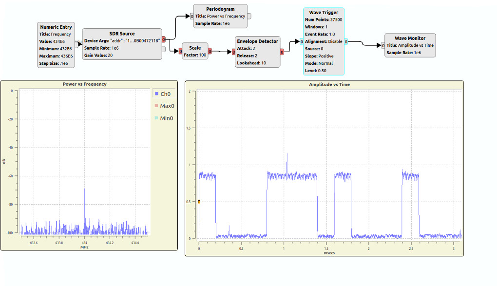
Since we have used this previously, let’s start by using Pothos. By adding an SDR source (with frequency control) and a “Wave Monitor” we have ourselves the simplest of all ASK receiving devices. Setting the tuning control to 433.9MHz and clicking the fob right next to the input antenna we can some tiny waves appear. This is the simplest of all receivers and as such it is not very good, to time for improvements.
Looks like we need some gain and adding a “Periodogram” at this point is a good idea. This is the same plot a spectrum analyser would give. We want a spectrum plot because it gives us an estimation when we start to distort with gain. Ideally we want the maximum gain before we start seeing distortion (e.g. more than 1 peak appearing) during a transmission. In our case 20dB was OK, whereas with much more gain and the signal started to distort.
When using the Periodogram we can see a large spike at the centre frequency. This is a DC component to the RF signal. We can remove this by using a DC removal block.
At this point the signal is still a little low, so we could:
- Digitally increase the gain of the signal
- Increase the visual gain of the plot
Getting out a magnifying glass would increase the visual gain, but let’s not get silly. The wave monitor has an “axis” control for this purpose, although this is not a good method of demodulating the waveform as it requires a slow human interface and even the fastest savant is terribly slow at demodulating signals and will miss much.
Let’s address these points. For gain we add a multiplying stage to increase the signal 20 fold (simple). Start with a simple decode method, the “Envelope Detector”. This control aims to detect the carrier envelope (when it’s on) and turn this into a digital output.

Adding a “Wave Trigger” on “normal” mode we can capture the signal (similar to an oscilloscope). The number of points can be adjusted on the Wave Trigger and Wave Monitor to view the whole transmission. If the code is static this is enough to manually decipher or save to file. There we have it: a simple, but effective (albeit manual) ASK receiver.
The elephant in the room: GNU Radio
So far we’ve skirted round GNU Radio. Pothos has very close links to GNU Radio, is similar in many ways and it also has support for GNU radio integration. Having used the Pothos GUI, the GNU Radio Companion GUI should feel familiar. If you have not installed it, then go ahead and install it now.
Just like Pothos our flow will be the same: Radio > Gain > Demod > Analysis. To use LimeSDR with GNU Radio we need to implement an “osmocom Source” with the device arguments “driver=lime,soapy=0”.

At this point we need to point out a few important differences from Pothos. Starting a new file we automatically get 2 blocks. The first is “Variable”, which is the variable “sample_rate”. This does what it says on the tin and holds our sample rate to be used by all the controls. The other is the “Options”, which contains some set-up options. We need to alter the sample rate to 1e6 (1Msample/s) and “Generate options” to WX — do this by double clicking the modules. The QT/WX are different visualisations and since we want to use WX later we need to change to these.
Using GNU Radio we have a lot ways of regenerating the ASK waveform we previously produced in Pothos. We used some combination of the blocks below, but this is not the only way it may be a good time to experiment and see if you can make a bespoke or unique solution at this point:
- Using A DC blocking block
- Using an RMS block
- Using a thresholds block
- Using a Freq Xlating FIR Filter
- Using the AM modulation block
- Using the Clock Recovery MM
Given our aim is to produce an ASK decoding device let’s take the most expedient path to that. To this extent the Clock Recovery Module may be the best choice, as this will work best for data recovery to binary data to save to file. We found this a complicated module to design in and so much so, we are certain the configuration below is sub-optimal and getting the best out of this module is not simple. The only parameter we adjusted was the “omega” value. Through a little trial and error an acceptable initial value of 18 was chosen. Our sample rate was 1Msample/sec. This is a “finger in the air” guess as we did not know the final symbol rate yet. Note if using a wave monitor the sample rate now becomes “samp_rate/samp_per_sym”.

The Clock Recovery Module worked better for us when we had already removed the carrier, as this seemed to confuse everything. This can be achieved by using the AM block. Another way is using the RMS block to create an envelope detector. To use this with the Clock Recovery Module the waveform needs offsetting around zero by adding a negative constant. Add in a binary slicer and a file sink and amazingly this is a ASK sampling device!

Hold the applause! It’s not actually that amazing, because the output format still needs interpreting. To parse the data is a topic in its own right, but there are programs out there that will do this for us and one example of a parser is “grc_bit_converter”. We ran the output data via this parser and got the result below. We can clearly see the preamble and then a string of bits.

From this data it’s clear that we have way too many samples per bit, therefore it’s likely our omega value is incorrect. Increasing the omega value to 25 gives less bytes per bit, but is still incorrect.
At this point we could continue to fine tune or better still, measure and calculate the correct omega value. However, for the purposes of decoding the stream this should be enough.
The data looks like we get around 1 to 1.5 bytes per bit currently — way too much — but from this it’s fairly easy to programmatically pick out the pattern we are looking for. Less than A0 is a zero and above 0xA0 could be a one, for example. Single bytes would be a single bit and triple would be two bits. More refinement would be nice but is not necessary.

Comparing this assumption to the waveform from our envelope detector, we can see that it ties in nicely, giving us confidence that everything is working (to a degree). This is a good point to break until next time, but feel free to adjust the model and continue to refine it.
Final words
Having achieved a result that looks to be getting there, that is all we have time for in this instalment. There are many improvements that could be made, such as AGC, for example. There will be more solutions to this issue and is often the case with programming, there are many ways to achieve a goal and some are better than others. If we simply wanted to see the waveforms, Pothos and a Wave Trigger would have been fine. If we wanted to sniff for all ASK transmissions and decode them on the fly, the Clock Recovery Module would be better. On a side note: recording ASK transmissions can be fun, but it should go without saying, please use this for good not evil!
If this was not quite enough ASK for you, we hope to see you next time when we will expand on this work further.
Karl Woodward